-40%
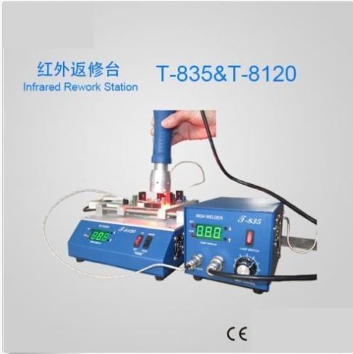
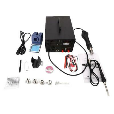
BGA IRDA Welder T835 with Preheating Oven T8120 work AC110V ( US Stock)
$ 174.23
- Description
- Size Guide
Description
BGA IRDA WELDER T835 + Preheating Oven T 8120CE Approved
100 Original%
Features:
1. The machine selects the infrared highly effective component to give off heat which independent exploration, adopt advanced PID intelligent controlling warm heating technology, controls warm precisely.
2. Can achieve to heat PCB board and component which contains lead or not,especially suit to BGASMD.
3. Use infrared heat, easy to cut through, heat proportion, don’t have sirocco flow. Don’t shift the small component on the PCB board,ensure the welding quality.
4. This machine has 600W heating system, widely to 120x120mm.Can use with the handhold infrared welder T-835.
5. Easily operate, can operate it through easy training.
Parameter:
Work floor size
200x240mm
Rated voltage and frequency
AC
110V
/AC
220V 60/50Hz
Complete machine power
800W
Preheating chassis power
600W
Preheating chassis size
120x120mm
Preheating chassis temperature adjustable
0-450
Main Component:
Preheating oven main body
1
Temperature sensor
1
Board support of the circuit
1
Power line
1
User manual (compact disc)
1
Technical parameter
Rated voltage and frequency
AC220v/AC110v/50-60Hz
Complete machine power
300W
Infra-red lamp power
100W
Infra-red lamp heating size
Φ35mm
Adjustable temperature of Infra-red lamp
0-350
Main Parts
Name
Model
Quantity
Welding table
T-835
1
Infra-red lamp
1
Temperature sensor
K-degree
1
Infra-red lamp holder
1
Power cable
0.75x1.8m
1
user manual(Compact disc))
1
6. Operation method
6.1.Starting and inspections before starting:
. Check if the cables of infra-red lamp, temperature sensor and power supply were connected well or not before starting.
. Turn on the power supply switch. Then let the machine work till Self-checking is finished. (Temperature displayed after self-checking is your room temperature.)
. Switches on the front panel are used to control the work process of infrared lamp. Press the front panel “” up button, “” down button to adjust the temperature of infrared lamp between 0-350. Press the switch “ON” to let infrared lamp work; press the switch “OFF” to stop working.
6.2. Sealing off/repair operation:
6.2.1 P
CB board laying aside:
Will elect well the PCB board select the appropriate working position.
6.2.2
Before sealing off/repair adjustment and preparatory work:
.According to the chip size and the welding technological requirement, selects the suitable infrared lamp the heating temperature(0-350 adjustable). When the sealing off is smaller than the 15x15mm chip, may adjust the infra-red lamp temperature to 160-240 about; When the sealing off/repair is smaller than the 20x20mm chip, may adjust the infra-red lamp temperature to 220-240 about; Opens in a big way, when 30x30mm chip, according to the craft and the user experience, may adjust the infra-red lamp 240-260; about.
Adopt infrared heat lamps no steps, you can adjust the size according to chip temperature freely. When the infrared heat lamps adjustment knob to adjust the largest, most powerful infrared light line, warming up faster chip, in the process of welding special attention to temperature control, to prevent displacement temperature senor chips not lead to heat a long time, heating up too high, burned chips.
.Regulation infrared temperature senor lights, place it in the chips or aside suitable location nearby. Chip in and around the senor head painted Flux(welding or welding-oil),this would enable senor measured the temperature more accurately, while helping the solder flux role, BGA pad will be more intact, can effectively prevent the pads from the stick and tin from the hair, and other issues.
6.3. Soldering / unsoldering operation:
6.3.1
. Fix the PCB board: Put the PCB board to suitable place.
6.3.2
. Preparation and adjustment before soldering/unsoldering:
Adjust infra-red lamp input temperature between 0-350 according to Chip’s size and requirements of welding technology. Set temperature between 160-240 to unsolder chips which size is under 15x15mm size; between 220-240 to unsolder chips under 20x20mm; adjust the temperature between 240-260 to unsolder chips over 30x30mm.
This machine adopts stepless methods to regulate temperature. When you regulate infra-red lamp to max power, infra-red lamp releases the strongest rays to make chip’s temperature rise fastest. In the process of welding, please pay attentions to temperature control sensor to avoid burning chips because of high temperature.
Put the temperature sensor at the suitable place near the Chip. Spread flux on the head of sensor for accurate temperature; spread flux around the chip to guarantee better welding.
6.3.3
Unsoldering/ soldering process:
6.3.3
.1. Unsoldering process:
. Fix PCB board.
. Place the temperature sensor, spread flux, set infra red lamp work temperature, then start infra red lamp.
. Adjust the place of infra red lamp to make the facula on the chip.
. Adjust the height of lamp to keep the height between 20-30mm. When the temperature is risen to your preset temperature or tin pan melt, please use vacuum suction or tweezers to remove chip, then power off the infra red lamp.
. Switch off the power after the machine completely cooled down.
6.3.3
.2. Unsolder all kinds of needle-socket, such as CPU, GAP, users need buy an infra preheat box.
General operation: First cover the PCB board that needn’t repair or that should be avoid high temperature with aluminum foil, fix PCB board well. Then set the preheat temperature between 160-180, put temperature sensor near the component you will unsolder or welding. Thirdly, start preheat chassis for 3-5 minutes or even longer time to make the component heated evenly. In some special conditions, please use infra red lamp as auxiliaries to heat quickly.
For the lead-free device, the temperature can be increased 20-30.
For two-faced board, please adopt lower preheat-temperature to preheat PCB board, supplemented by infrared heat at the top.
6.3.3
.3. Welding process:
Welding process is nearly same as unsoldering process, but users should pay attention to clean the tin pan or pads and ball-planting, put Chip on the right place before heating.
6.4. Attentions in the process of unsoldering/welding
. For some simply encapsulated chips, we suppose you put a small piece of aluminum foil on silicon position to prevent chips crack from overheating. The size of aluminum foil should be slightly bigger than silicon, otherwise, it will influence the welding effect.
. In the process of unsoldering/welding, all the plastic plug-in units within the scope of infra red lamp rays should be covered with aluminum foil to prevent deforming or damaging from high temperature.
.Clean and test the PCB board after cooled down.
. Please don’t let infra red lamp work for long time without PCB board. To let infra red lamp irradiate the articles with strong reflection is strictly forbidden, otherwise, the service life of lamp will be shorten.
6.5. Infra-red lamp maintenance:
. The preheating chassis and the infra-red lamp body, specially the infra-red lamp high insightful protection slide, should be regularly wiped off dust or condensate of flux by with dehydrated alcohol to keep infrared heat radiation unobstructed.
. Put hand-help lamp back to the support after use to make infra red lamp completely cool down.
7. Attentions:
. Don’t switch off the power after use till the fan fully cool down, which will prolong the service life of the machine.
. Keep the intake of ventilated and lamp clean. Clean the infra-red lamp high insightful protection slide regularly with dehydrated alcohol.
. Be careful of security under high temperature.
. Take out the power supply plug-in if don’t use for long time.
8. Maintenance Warranty
We guarantee the machine quality for a year. The service of infrared lamp is designed for 1000 hours. We guarantee the infrared lamp is used for three months.
Statement:
Above products information is only for reference, take the finial products as the goods criterion.
